How do I know if my capture unit is able to stream data?
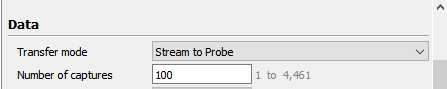
‘Streaming data’ is the ability to send data to the Exostiv Probe that exceed the storage reserved in the capture unit FPGA memory.
This mode of transfer is selected in the Exostiv Dashboard Analyzer (or the Exostiv Blade client) – the alternative mode being ‘burst to probe’.
In a first approach, the capture unit is able to stream data out if the bandwidth required to sample data (sampling frequency x number of bits) is lower or equal to the bandwidth available at the transceivers (SERDES).
However, there are additional parameters that condition this ability, like the internal granularity of the IP, the bandwidth efficiency of the DDR accesses in the Exostiv Probe (or Exostiv Blade), and so on. The following article provides a formal computation: ‘How many nodes can I sample continuously without creating overflows?’.
Exostiv Dashboard and Exostiv Blade client provide this information in their graphical interface – check the ‘Capture Unit Status’ section’ in the core inserter. This section is available for all capture units (see pictures below).
Software v2: Exostiv Blade and Exostiv Probe EP16000
The following parameters basically condition the ability of the capture unit to stream:
- The number of data probes – that is the ‘size’ (width) of the samples : this is defined on the ‘Capture configuration’ tab.
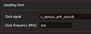
- The sampling frequency: this is defined from the choice of the sampling clock signals, and specified in the ‘Capture configuration’ tab as well.
- The available bandwidth on the transceivers : this is a ‘physical’ parameter that depends on the target board, how many transceivers are available and at which data rate they are configured. This is specified in the ‘Link Configuration’ tab.

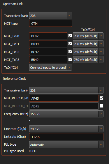
Any IP instance (standard IP or ext. width IP) uses up to 4 transceivers (one transceiver quad). Consequently, the maximum available streaming bandwidth of a specific IP instance is defined by its transceivers link. Typically it is currently 4 x 28.125 Gbps = 112.5 Gbps for the Blade and 4 x 16.25 Gbps = 65 Gbps for the EP16000 probe.
Additional parameters, like some necessary (small) overhead used on the transceiver link and data granularities have to be taken into account too.
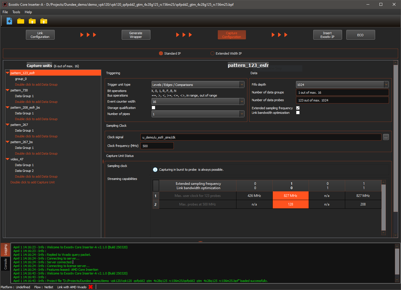
The ‘Capture Unit status’ area provides help about how the selected capture unit can be used to stream data:
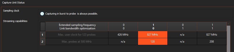
In the table, the following information is provided:
- Line 1: Maximum ability to stream for the specified number of probes. On this line, the software computes the maximum sampling frequency that can be used to stream the specified number of bits (number of data probes) within the limit of the link configuration (available bandwidth on the transceivers)
- Line 2: Maximum ability to stream for the specified sampling frequency. On this line, the software computes the maximum number of data probes that can be streamed over the transceivers with the selected capture unit, provided the transceivers setrings and the specified sampling clock frequency.
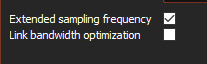
Please note: the IPs come with additional bandwidth optimization features:
- Extended sampling frequency: allows selecting a larger range of sampling frequencies.
- Link bandwidth optimization: adds logic to optimize the bandwidth at the transceives (at the cost of more resources)
These features can be selected from their controls…
… or by selecting the right option from the table.
The selected option is highlighted in the table.
Software v1: Exostiv Probe EP12000 and older
For the ‘Capture Unit Status’ to provide a correct information, the following data is required:
- The width of the capture unit in bits. In ‘Netlist insertion mode’, this value is automatically computed after the nodes to be observed from the target design are selected. In ‘RTL insertion mode’, this value is an input field that needs to be speficied when setting up core generation.
- The frequency of the sampling clock. Worth noting, this value is not automatically detected and must be provided. In Exostiv Dashboard, this value is optional; in Exostiv Blade client, this value must be entered. The value must be entered as MHz.
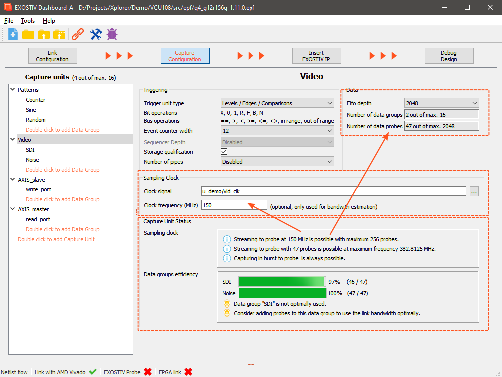
The ‘Capture Unit Status’ returns the following information:
‘Sampling clock’ subsection.
- Whether ‘streaming’ is possible or not at the specified sampling frequency. It also provides the maximum number of bit (max width) of the capture unit to be able to stream at the specified sampling frequency.
- It reminds the user that the ‘burst to probe’ mode remains a valid option, as it uses a flow control mechanism with back pressure to prepare and send bursts of data from a buffer implemented in the target FPGA memory.
For the specified capture unit width, it provides the maximum sampling frequency at which streaming remains possible.
‘Data groups efficiency’ subsection
In this section, the tool checks whether all data groups are populated with the specified number of bits. Capture units are generated using the largest of the multipexed data groups connected to it. If a data group is composed of a smaller number of bit, some reserved resources and bandwidth are basically wasted.